This is my own Plasma TV. Symptom, sudden power cut off. Power LED not lit at all when the side power button switched on. According to the service manual [ th_p42x30d_g_k_m_p_s_v_1.pdf ] , this is power board issue.
Trace further and narrow down the search to standby power section. Standby voltage (5V) is totally down.
B159-003 Power Board Block Diagram
This section on the B159-002 power board, component side.
B159-002 Power Board Component Side
This diode fails become short circuit, part of the secondary side of the transformer that feedback to FAN6754 PWM controller pin 2 (FB)
FAN6754 Typical Application schematics, not the actual schematics
It is B3100 diode that should be able to withstand 100V peak and 70V RMS reverse voltage
3.0A HIGH VOLTAGE SCHOTTKY BARRIER RECTIFIER
Replace this FML-G22S, the best I have currently, salvage from old PCB.
It can withstand 200V peak.
Now, I can see the 5V standby voltage. Put everything back together and test.
Will try to find the actual component soon (B3100) for replacement.
My old Dell E153FPC back-light recently failed to light up.Tracing lead me to the bad inverter circuit and broken CCFL back-light.
So replacing with an LED would be a great idea. Refering to Instructables, I'm planning to do the same thing but the LED flex/strip here cost more than a used/refurbished LCD monitor.
A cheap solution is by creating my own LED bar. 3 white LEDs in series with current limiting resistor. Calculated to works with 12VDC.
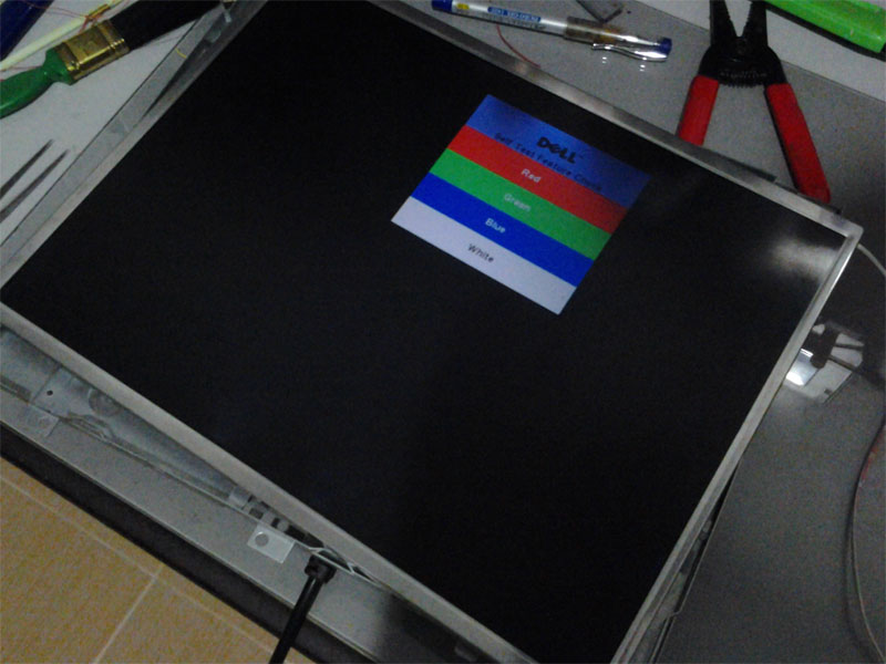
The CCFL backlights have been removed earlier but I did not snap any image during the process. Please Google for this. Next, test the LED back-light.
Does not look like what you expected? Wait until you turn it on.
Connect it to 12VDC source that can be found on the power supply board. A fuse added just in case. Use a detachable connector for easy troubleshooting later on.
Tadaa! although the light source does not emit its rays uniformly, but for me this is enough since I'm planning to use this monitor just for PC troubleshooting.
Finally, put them back together again. From now on, this monitor is no longer an LCD Monitor but an LED Monitor :-)
I have an electric water boiler and warmer AKA thermo pot which was struck by lightning. The circuit board was heavily damaged beyond repair.
But the good news is all other parts such as heating elements, DC motor pump and temperature sensor still OK. So this is how the project started.
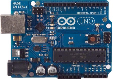
Before this project started, I did talk to my brother about Arduino. Sounds like fun. So I give them a try. I choose Arduino Uno for this project since it is highly recommended for a beginner.
Typical electric water boiler and warmer has 2 heating elements, boiler and warmer.
Boiler : 3A : 80Ω : 720W
Warmer : 0.6A : 390Ω : 144W
The DC motor pump working voltage is DC 9V.
I'm not sure what type of temperature sensor used by this boiler but from my study, it measures;
Around 100kΩ when 33°C (room temp)
Around 10kΩ when 100°C (boiled)
The question now is how to translate this value 100kΩ<=>10kΩ to 33°C<=>100°C? I start with a simple voltage divider, 5V DC, smoothing E capacitor and link them to Arduino pin A0 (AnalogInput)...
R5 = 10kΩ
C1 = 1µF
...wrote a simple program as below to get the AnalogInput value during both room temperature and boiled temperature.
16X2 LCD to show status and temperature. (pin D8 - D13). Notice that I ignore the contrast control pin? This because this LCD display is an old display that is having problem. :-( so I leave the pin open.
Unlock button, using Interrupt (pin D2) that will enable the pump and light up the LCD back-light for a period of time. I'm too lazy to built the Debounce module for this button so I use a capacitor :-)
Outputs (pin D5 and D6) to turn on boiler and warmer thru transistors and relays.
Buzzer (pin D4) for overheat alert, 1kHz tone.
Complete schematic diagram
Flow chart below would explain the system flow.
Complete Arduino sketch
#include <LiquidCrystal.h>
LiquidCrystal lcd(13, 12, 11, 10, 9, 8); int sensorPin = A0; //temp sensor analog in pin int samplingRate = 500; //sampling/pulse rate int unlockInt = 0; //interrupt value not pin int unlockTimer = 10000; //unlocked timer in msec int unlockTimerCount = 0; int lcdBackLightPin = 7; //lcd backlight signal pin int lcdBackLightState = LOW; //lcd initial state int warmerPin = 5; //warmer signal pin int boilerPin = 6; //boiler signal pin boolean boiling = false; int boiledTimer = 10000; //in msec int boiledTimerCount = 0; int warmLowLimit = 80; int warmHiLimit = 85; int reboilTemp = 65; int boiledTemp = 95; int emcyTemp = 105; int buzzerPin = 4; int buzzerFreq = 500;
void setup() { //Serial.begin(9600); // set up the LCD's number of columns and rows: lcd.begin(16, 2); lcd.setCursor(0, 0); lcd.print("Temp =");
//set up unlock int pin attachInterrupt(unlockInt, unlock, RISING);
//set lcd backlight signal pin pinMode(lcdBackLightPin, OUTPUT);
The flow is quite similar to the original design and other model/brand. Reboil at 65°C, stop boiling several minutes after 95°C, cut off at 105°C. I did salvage an old circuit board from a different model of boiler and found 3 thermostats 65°C, 95°C and 105°C. So I guess all boilers are using the similar flow.
The final test...
Next is to built a proper circuit board and put it back together in one piece.
Since M1-DA to VGA cable is quite expensive, we have decided to add extra connector to our Dell 3400MP Projector so we could just use common male to male VGA cable.
1st thing to do is to know the connector pin-out. For VGA connector we have 15-pin connector.
Cable = MALE and Projector = FEMALE.
Next, the M1-A connector (AKA M1-P&D Plug) A lot of pin. :-)
Cable = MALE and Projector = FEMALE.
Internet research tell me that only 7 connections are needed in order to make this work as below
>
VGA pin#
M1 pin#
Red
1
C1
Green
2
C2
Blue
3
C4
RGB
Ground
6,7,8 (join)
C5
Horizontal
Sync
13
5
Vertical
Sync
14
6
Sync
Ground
10
4
Now the hard work begin.... disassembling...
Soldering...
Testing...
Finally, the connector cut-out through the Dell 3400MP magnesium alloy chassis.


