DIY IR interface

This circuit is also from www.electronics-lab.com.
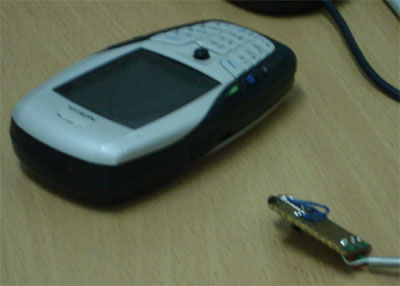
Since it is very hard for me to get the infrared interface (TFDU4100), I start to look in the old/damage handphones.
It looks something like this.


Now, you need to remove it using the hot air blower perhaps.

Connecting to motherboard
Please refer to www.electronics-lab.com
on how connect this irda module to your motherboard.
My IrDA


Infrared Transceiver Modules
Here are the pin layout and picture of the device.


Pin Description of TFDU4100
| Pin Number | Function | Description | I/O | Active |
|---|---|---|---|---|
| 1 | IRED Anode | IRED anode, should be externally connected to VCC2 through a current control resistor | ||
| 2 | IRED Cathode | IRED cathode, internally connected to driver transistor | ||
| 3 | Txd | Transmit Data Input | 1 | High |
| 4 | Rxd | Received Data Output, open collector. No external pull–up or pull–down resistor is required (20 k. resistor internal to device). Pin is inactive during transmission. | 0 | Low |
| 5 | NC | Do not connect | ||
| 6 | VCC1/SD | Supply Voltage / Shutdown | ||
| 7 | SC | Sensitivity control | 1 | High |
| 8 | GND | Ground |
No comments:
Post a Comment